

How Do You Identify Correct Vintage CB Radio Parts?
Last Updated: November 1, 2026
Quick Summary
To identify correct vintage CB radio parts, first identify the radio itself by checking the label and the board code, since the chassis revision determines which parts fit. Then match the part by package type, pinout, mounting, and connectors before ordering. Test any used or suspect part before installing it.
- On most 1970s and 1980s sets, the label sits on the back panel, under the top cover, on the bottom plate, or inside the battery compartment.
- The final transistor is usually the largest transistor in the output section, often bolted to a metal heat sink.
- TO-220 style transistors have a rectangular plastic body roughly 10 mm wide with a metal tab and three legs in a row.
- A white, cloudy getter flash means air got into a tube, so the tube is dead.
- Photograph both the top and solder side of your board before removing any part.
Table of Contents
- Start With the Radio, Not the Part
- CB Radio Model Number Lookup: Finding Your Chassis ID
- CB Radio Final Transistor Identification: Finding the Output Stage
- Tubes, Rectifiers, and Glass Components in Older Sets
- CB Radio Parts Compatibility: What Actually Swaps Between Models
- Identifying Parts From Photos When Markings Are Gone
- Buying Used CB Radio Parts Without Getting Burned
- Matching Your Part to the Right Replacement at Scott Radio
- Frequently Asked Questions
Start With the Radio, Not the Part
The first rule of identifying correct vintage CB radio parts is simple: identify the radio before you touch a single component. Our step-by-step vintage CB radio restoration guide walks through the whole job with part identification in context.
Buying a knob or a final transistor based on a photo alone is a common way to end up with a part that will not mount on your set.
CB Radio Model Number Lookup: Finding Your Chassis ID
A CB radio model number lookup starts with the label, then moves to the board itself. The label gives you the brand and model. The board markings can help confirm the revision. Checking both before you trust a part listing is a sound habit.
Where the Label Hides on 1970s and 1980s Chassis
On most 1970s and 1980s sets, the label sits in one of four places:
- The back panel, near the antenna socket
- Under the top cover, stuck to the chassis frame
- On the bottom plate, often worn from years on a dash
Labels can fade, peel, and get swapped between radios, so a label alone is not always proof of the model.
Reading Component Numbers and Markings on the Board
Board markings are the harder half. Look for an etched or printed code near the edge of the main circuit board. Many sets also carry a brand name and model stamped on the board itself.
If the label is gone, work from the board outward, starting with the board code and confirming the model from there. Our step-by-step vintage radio model identification guide walks through the process.
CB Radio Final Transistor Identification: Finding the Output Stage
CB radio final transistor identification means finding the transistor closest to the antenna output on the main board. That part handles the transmit power. It is usually the largest transistor in the output section, often bolted to a metal heat sink.
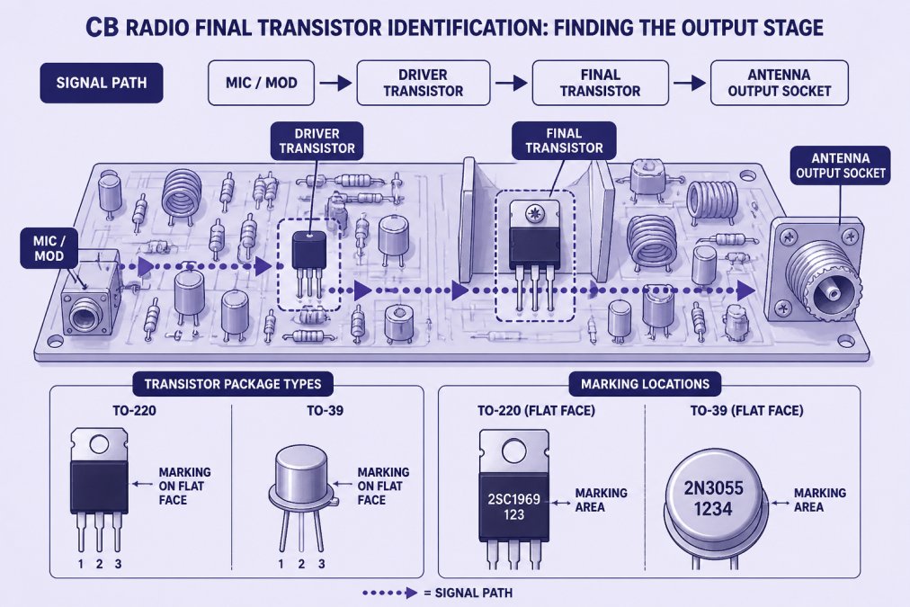
Power Transistors, Drivers, and Finals: Telling Them Apart
Three parts sit in the transmit chain, and they are not interchangeable:
| Part | Job | Where It Sits | Package Type |
|---|---|---|---|
| Driver transistor | Boosts the signal | Before the final | Small, TO-39 style |
| Final transistor | Sets transmit power | Next to the antenna output | Larger, TO-220 style |
| Power transistor | Regulates supply voltage | Near the power socket | Bolted to chassis or heat sink |
The final is the one most people need. Read the part number printed on its flat face, then match package type and pinout before you order. A part with the right number but the wrong pinout will not work.
Reading the Package and Pinout Before You Order
Most vintage finals fall into two physical families, and the package tells you almost as much as the number:
- TO-220 style: a rectangular plastic body roughly 10 mm wide with a metal tab and three legs in a single row. The tab is usually the collector and is often bolted to the heat sink. Pin spacing is about 2.5 mm.
- TO-39 style: a small round metal can about 9 mm across with three leads on a circle. Drivers and older finals often use this package. The can itself is frequently the collector.
Pinout order is not standardized across part numbers. Two transistors can share a package and a power rating but swap base and emitter, which means the radio will not bias correctly and may fail on transmit. Before you buy, confirm three things against a datasheet or a known-good board:
- The pin order (for example, base-emitter-collector versus emitter-base-collector).
- The package outline and mounting hole spacing.
- The voltage and current rating, not just the part number.
A common pattern is a final that reads correctly on a multimeter but is a substitute with a different gain band. It may key up and produce low or distorted output. If the original number is unavailable, treat any substitute as a new design and verify the bias point, not just the pinout.
Testing a Final Safely Before It Goes In
Test first, install second. Power the radio down, unplug it, and let the filter capacitors discharge before you touch the board. Large electrolytics in the power supply can hold a charge long after the cord is pulled.
With the final out of circuit, use a multimeter on the diode-check setting:
- Base-to-emitter and base-to-collector should read like a forward-biased junction in one direction and open in the other.
- Collector-to-emitter should read open both ways on a good part.
- A short across any pair means the part is dead and must not be powered up in the chassis.
Once the part passes, compare its mounting to the heat sink before soldering. Insulator pads and thermal compound matter: a final bolted directly to a grounded heat sink without the right insulator can short the collector to ground.
Tubes, Rectifiers, and Glass Components in Older Sets
Tubes and rectifiers belong to the oldest gear in the hobby. A tube amplifies or rectifies a signal inside a glass envelope. A rectifier converts AC to DC in the power supply.
Check for three things before you replace one:
- A white, cloudy getter flash means air got in, so the tube is dead
- Loose or rattling parts inside the glass mean the tube is failing
- Burn marks or a dark ring on the glass point to heat stress
Handle glass parts by the base, never the envelope. Oils from your fingers can crack hot glass. Match the tube number exactly, and check the socket type before buying.
Browning R-27 Variable Tuning Capacitor →
CB Radio Parts Compatibility: What Actually Swaps Between Models
CB radio parts compatibility comes down to three checks: mounting, connectors, and markings. A part that passes all three will usually work. A part that fails one will not, no matter what the listing says.
| Check | What to Compare | Why It Matters |
|---|---|---|
| Mounting | Hole spacing, screw size, bracket shape | A board or knob that will not bolt down is useless |
| Connectors | Plug type, pin count, wire color order | Wrong plugs mean rewiring or a dead part |
| Markings | Part number, package type, pinout | Same number in a different package may not fit |
A common mistake is assuming two radios from the same brand share parts. They often do not. When you compare a candidate part, our guide on verifying vintage radio part compatibility covers the tests that catch near-misses before you pay.
Identifying Parts From Photos When Markings Are Gone
Photos can still get you close when the markings are worn off. Work from shape, position, and neighbors. This is the step most restoration guides skip, and it is where a structured visual workflow saves the most wrong orders.
A Four-Step Visual Workflow
- Package outline. Is it a round metal can, a rectangular plastic body with a tab, a glass envelope, or a molded plastic block? The outline narrows the candidate list faster than any other single clue.
- Pin count and layout. Count the leads and note whether they sit in a row, on a circle, or in two rows. A three-lead part in a row is a different animal from a three-lead part on a circle.
- Board location and neighbors. A part next to the antenna socket is likely in the output stage. A part near the power socket is likely a regulator. A part beside a crystal is likely in the oscillator or mixer. The circuit neighborhood tells you the role even when the number is gone.
- Circuit role. Trace the traces and look at what the part connects to. A part with one leg to ground and one to a coil is probably a bypass or tuning element. A part in series with the antenna line is in the transmit path.
What Each Clue Rules In and Out
| Clue | What It Suggests | What It Rules Out |
|---|---|---|
| Round metal can, 3 leads on a circle | TO-39 style transistor, often a driver or older final | Power regulators and large finals |
| Rectangular body with metal tab, 3 leads in a row | TO-220 style transistor, often a final or regulator | Small-signal parts and tubes |
| Glass envelope with a base | Tube or rectifier | Any solid-state part |
| Molded block with many pins | Connector, transformer, or filter | Discrete transistors |
Photographing Your Own Board Before Removal
Insider tip: photograph your own board before you remove anything. A clear "before" shot of the whole board saves hours when you reassemble.
A common pattern is a restorer who photographs the top of the board but not the solder side. Shoot both. The solder side shows which pads connect and often reveals a part's role faster than the top.
Once you have a candidate, confirm it against the compatibility checks in the next section before you buy.
Buying Used CB Radio Parts Without Getting Burned
Used CB radio parts are the practical route for most vintage sets, because new production stopped decades ago. The risk is real, though. Untested pulls from scrap radios fail often, and returns are rarely offered.
Ask three questions before you buy:
- Was the donor radio tested and working before disassembly?
- Are the photos of the actual part, or a stock image?
- Is the return policy clear if the part does not fit?
Testing a Used Part Safely Before It Goes in the Chassis
Test first, install second. Power the radio down and unplug it. Check the part for cracks, burn marks, and bent pins.
Watch out: never power up a radio with a suspect final transistor installed. A shorted final can take out the driver and the power supply with it.
For sourcing advice that focuses on tested parts, read our guide on buying tested vintage radio parts with confidence.
Matching Your Part to the Right Replacement at Scott Radio
The safest way to avoid a wrong part is to buy from a seller who organizes stock by brand and model.
Here is what that looks like in practice:
- A Browning R-27 variable tuning capacitor at $30.00, pulled from a tested working set
- A Midland 1001Z control potentiometer pair at $25.00, matched as a pair
- A Realistic TRC-418 main circuit board assembly at $40.00
- A PACE CB-145 main circuit board assembly at $45.00, tested and working
Each listing tells you the donor radio was tested before disassembly. Read our CB radio repair parts fit guarantee to know what is covered before you buy.


Jack Scott personally oversees the customer experience, so if you are unsure which part fits your set, ask before you order.
Frequently Asked Questions
How do I find the model number on a vintage CB radio?
Check the back panel and the bottom of the chassis first. Most 1970s and 1980s sets carry a sticker or stamped plate with the brand and model, such as Midland 1001Z or Realistic TRC-418. If the sticker is gone, look inside the case for a paper label on the board or a stamp on the chassis frame. Write down every number you find, including any FCC ID, because sellers use those to confirm which board and knobs fit your radio.
How can I tell which replacement part fits my CB radio?
Match three things before you buy: the model number, the physical mounting pattern, and the connector or pin arrangement. Compare the part number stamped on the original component with the listing photos. A main board from a Realistic TRC-418, for example, will not drop into a different chassis even if it looks similar. When compatibility with other models has not been verified, treat the part as a match for its donor model only.
Can parts from one CB radio model work in another?
Sometimes, but rarely without checking. Knobs, potentiometers, and crystals cross over more often than main boards because they follow common shaft sizes and frequencies. Final transistors and tuning capacitors are usually model-specific. Before assuming a swap will work, compare the part number, the mounting holes, and the lead spacing side by side. If a seller has not verified compatibility with your model, plan on measuring the original part yourself.
How do I check whether a used CB radio part is compatible and still good?
Ask the seller whether the donor radio was tested and working before disassembly, and request photos of the actual part with its markings visible. On arrival, inspect for oxidation, cracked solder joints, and cut leads that need reconnection. Test a used board or transistor on a bench supply before installing it, and never power up a chassis with a suspect final transistor still in circuit. Buying from a seller who organizes parts by brand and model shortens this whole process.
Identifying correct vintage CB radio parts takes patience, but the payoff is a radio that works the way it did when it was new. If you are stuck on a chassis code or a worn transistor number, send us a photo and the model. Get started with SCOTT RADIO & ELECTRONICS and find the part your set actually needs.
