

How to Choose a Vintage Radio Transformer That Fits
Last Updated: November 16, 2026
Quick Summary
To choose a vintage radio transformer, first decide whether the radio needs a power transformer or an audio output transformer, then match its voltages, current and mounting to the schematic. Check the part's primary and secondary windings before installing it.
- A power transformer feeds the rectifier and tube filaments from the wall outlet.
- An audio output transformer sits between the output tubes and the speaker.
- Calculate each secondary winding's voltage times current, then sum the results for total VA.
- Measure each winding's resistance and check for shorts to the core before installation.
- Confirm the primary voltage matches your mains, such as 117 volts in the United States.
Table of Contents
- Power Transformer vs. Audio Output Transformer: Knowing Which You Need
-
Identifying Your Radio's Transformer Requirements From the Schematic
- Step 1: Locate the transformer on the schematic
- Step 2: Record the primary voltage
- Step 3: Record each secondary voltage and its current draw
- Step 4: Convert the loads to volt-amperes
- Step 5: Note the mechanical and connection details
- Step 6: Write the specification sheet
- Matching Primary and Secondary Voltages
- Reading Winding Leads and Chassis Mounting
- How to Test a Radio Power Transformer Before Installing It
- Sizing the Transformer: Current, VA and Power Margin
-
Audio Output Transformer Impedance Matching and Tube-to-Speaker Pairing
- The reflected-load relationship
- Step 1: Find the tube's recommended plate load
- Step 2: Find the speaker impedance
- Step 3: Calculate the required turns ratio
- Step 4: Check the candidate against the calculation
- Step 5: Account for frequency response and power handling
- When the original markings are gone
- Reading the Vintage Radio Transformer Wiring Diagram
- Safety Checks for Live-Chassis and Transformerless Radios
- Ordering Your Replacement Transformer From Scott Radio & Electronics
- Frequently Asked Questions
Power Transformer vs. Audio Output Transformer: Knowing Which You Need
The power transformer is the big, heavy block with a mains primary and several secondary windings.
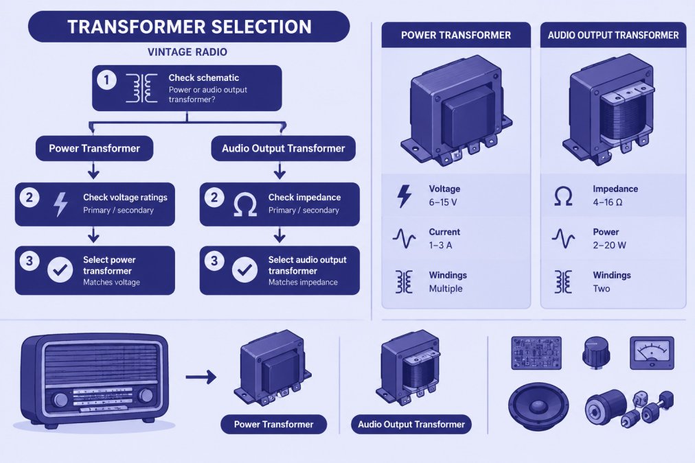
The audio output transformer is smaller.
Many hobbyists mix these two up when they shop. Look at the schematic first.
For a replacement power transformer board, see our Power Transformer Board For Cobra 1000 Gtl Cb Radio.
Identifying Your Radio's Transformer Requirements From the Schematic
The schematic and the service data are the only reliable source of transformer requirements. A repeatable workflow can turn a schematic into a written specification you can hand to a seller or compare against a listing. Work through the steps below in order and keep the results on one sheet of paper.
Step 1: Locate the transformer on the schematic
Find the transformer symbol that connects to the AC line cord and the rectifier. That is the power transformer. Note every winding drawn on the symbol: the primary, the high-voltage secondary (often center-tapped), the filament or heater winding, and any auxiliary winding such as a bias or pilot-lamp supply.
Step 2: Record the primary voltage
Some sets have a multi-tap primary (for example 105, 117, and 125 volts) so the set could be matched to local line voltage. Write down the tap the schematic specifies. A transformer whose primary is rated only for 230 volts is not a drop-in replacement for a 117-volt set.
Step 3: Record each secondary voltage and its current draw
The schematic gives the voltage. The current usually comes from the service data or must be estimated from the tube lineup. For the high-voltage secondary, add the plate and screen currents of every tube fed by that winding, using the tube manual values for the operating point shown on the schematic.
Step 4: Convert the loads to volt-amperes
Multiply each secondary voltage by its current to get volt-amperes, then add the results. A high-voltage winding delivering 300 volts at 0.1 amps is 30 VA; a 6.3-volt winding at 3 amps is about 19 VA; together the radio needs roughly 49 VA before margin.
Step 5: Note the mechanical and connection details
Record the mounting style (vertical shell, horizontal shell, or bracket), the bolt spacing and slot dimensions, the overall height, and the lead count and color code. These details decide whether a transformer that is electrically correct will actually fit and wire into the chassis.
Step 6: Write the specification sheet
Combine the results into a single list: primary voltage and tap, each secondary voltage and current, total VA, mounting footprint, and lead count.
Watch out: service data sometimes lists a transformer part number without ratings, and substituting by part number alone can hide a different secondary voltage or filament current.
Matching Primary and Secondary Voltages
Voltage matching is where most purchases go wrong. The primary must match your mains voltage.
The secondary voltages must match what the radio's circuit expects. A higher high-voltage secondary can overstress the rectifier and filter capacitors. A lower one can leave the radio weak or silent.
Reading Winding Leads and Chassis Mounting
Physical fit matters as much as electrical fit. Check the mounting footprint, the bolt pattern, and the overall height.
Count the leads, too. Many vintage transformers use colored leads with a standard color code. Compare the lead count and colors with the wiring diagram.
How to Test a Radio Power Transformer Before Installing It
Never install a transformer you have not tested. A shorted winding can burn out a new rectifier, damage the power switch, or start a fire. Test first, then wire it in.
Work through the tests in order. Stop if a test fails.
Checking Winding Continuity and Resistance
Set your multimeter to resistance (ohms). Measure each winding separately:
- Measure the primary winding. You should read a low, steady resistance, often a few ohms. An open reading (no continuity) means a broken winding.
- Measure each secondary winding. The high-voltage winding will read higher than the filament winding, as expected.
- Compare each reading with the service data if you have it.
A winding that reads open has a break somewhere inside. Do not use that transformer.
Checking for Shorts and Insulation Faults
Next, check that the windings are not shorted to each other or to the core. A short can be hard to spot by eye, so test for it.
- Measure between each winding and the metal core. You should read open or very high resistance. A low reading means insulation breakdown.
- Measure between separate windings. Again, you want open or very high resistance.
Unplug the radio before any measurement, and test the core as well. Unplug the radio before any measurement, and always test the core.
Sizing the Transformer: Current, VA and Power Margin
A transformer must supply enough power. Its rating is usually given in volt-amperes (VA).
For example, a secondary delivering 300 volts at 0.1 amps needs 30 VA.
Then add a power margin.
The article gives these sizing rules and figures for judging whether a transformer has enough capacity.
| Item | Value | Note |
|---|---|---|
| Power unit | Volt-amperes (VA) | Rating used to size a transformer |
| Example winding | 300 V at 0.1 A | Needs 30 VA |
| Calculation | Voltage × current, summed | Add every secondary winding |
| Power margin | Rated above calculated load | Leaves room for heat and aging |
| Undersized rating | Far below calculated load | Transformer will overheat |
Audio Output Transformer Impedance Matching and Tube-to-Speaker Pairing
An audio output transformer does one job: it reflects the speaker's low impedance up to the high plate load the output tube wants to see. Getting that reflection right is the whole game, and it is the part most buying guides skip. The relationship is set by the turns ratio, and you can work it out with arithmetic rather than guesswork.
The reflected-load relationship
The impedance ratio between primary and secondary equals the square of the turns ratio. If a transformer has a 25:1 turns ratio, the impedance ratio is 625:1. Connect an 8-ohm speaker to the secondary and the tube sees about 5,000 ohms at the primary.
Step 1: Find the tube's recommended plate load
The tube manual lists a recommended plate-to-plate load for a given operating point. For a single-ended 6V6 or 6AQ5, a common figure is in the 5,000-ohm range; for a push-pull pair of 6V6 tubes, the plate-to-plate figure is typically around 8,000 to 10,000 ohms.
Step 2: Find the speaker impedance
The speaker frame usually prints the voice-coil impedance, commonly 3.2 or 8 ohms in vintage sets. Measure the DC resistance with a multimeter as a sanity check: a nominal 8-ohm speaker typically reads a little under 8 ohms DC, and a 3.2-ohm speaker reads around 3 ohms. If the reading is far off, the speaker may be damaged or replaced.
Step 3: Calculate the required turns ratio
Divide the tube's recommended load by the speaker impedance to get the impedance ratio, then take the square root for the turns ratio. A 5,000-ohm load into an 8-ohm speaker gives an impedance ratio of 625 and a turns ratio of 25:1. A 10,000-ohm load into a 3.2-ohm speaker gives about 3,125 and a turns ratio near 56:1.
Step 4: Check the candidate against the calculation
A transformer rated for a 5,000-ohm primary and an 8-ohm secondary is a match for the first example. A transformer rated for 10,000 ohms into 4 ohms is not a match for either example and will reduce power and shift the frequency response. If the listing gives only a turns ratio, square it to get the impedance ratio and compare.
Step 5: Account for frequency response and power handling
The output transformer's core and winding geometry set its low-frequency and high-frequency limits.
Watch out: a transformer with the right impedance ratio but the wrong phase connection in a push-pull circuit will cause distortion or oscillation. Confirm the plate and screen lead assignments against the schematic before soldering.
When the original markings are gone
If the old transformer has no readable ratings, measure the turns ratio directly. Apply a low AC voltage to the primary from a signal generator or a small filament transformer, measure the voltage on the secondary, and divide. The voltage ratio equals the turns ratio, and squaring it gives the impedance ratio.
Reading the Vintage Radio Transformer Wiring Diagram
A wiring diagram shows how each lead connects. Before you wire a new transformer, trace the old one lead by lead.
Match the new transformer's leads to the same functions: mains primary, high-voltage secondary, filament winding, and any center taps. Double-check against the diagram before you apply power.
Safety Checks for Live-Chassis and Transformerless Radios
Some vintage radios have no power transformer at all. These are often called AC/DC or transformerless sets.
Treat any transformerless radio with extra care:
- Use an isolation transformer when you power up and test the set.
- Never touch the chassis while the radio is plugged in.
- Discharge large filter capacitors before working inside.
Before you buy any replacement part, confirm whether your radio needs a power transformer at all. See 7 Proper Storage Rules for Vintage Radio Electronics for practical guidance.
Ordering Your Replacement Transformer From Scott Radio & Electronics
Once your schematic notes, tests, and sizing calculations match a candidate part, you are ready to order. Our Radio Shack Navaho Power Transformer TP-055 is listed at $25.00, our Browning Mark III Golden Eagle Power Transformer at $45.00, and our Lafayette Comstat 25B Power Transformer at $25.00.
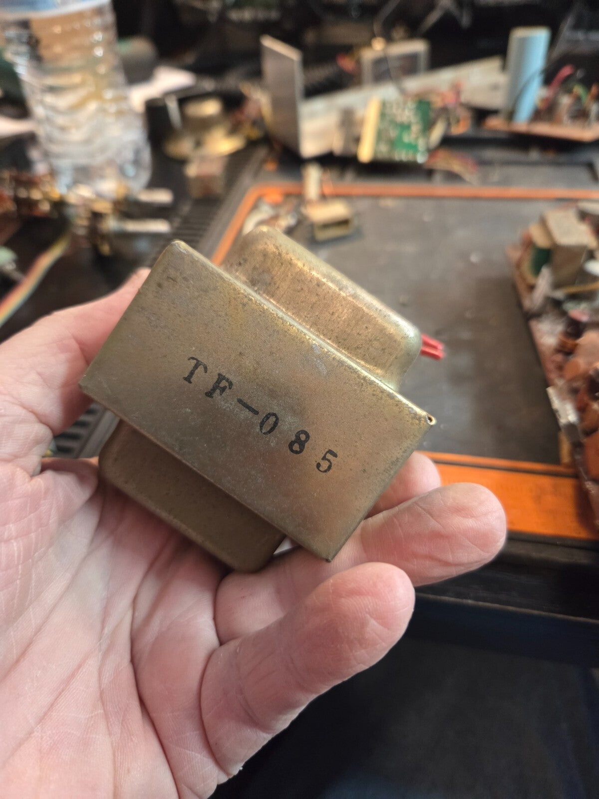
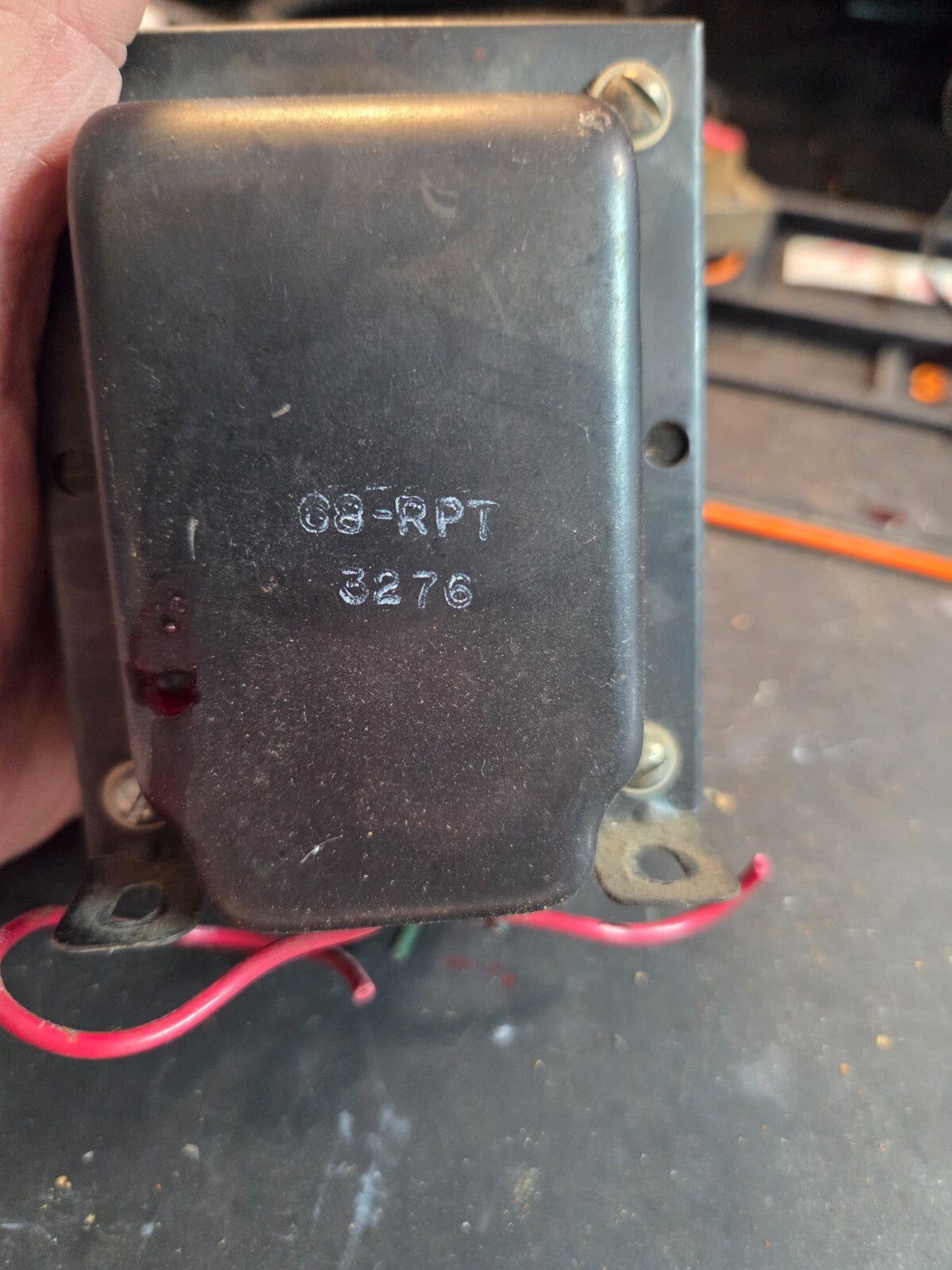
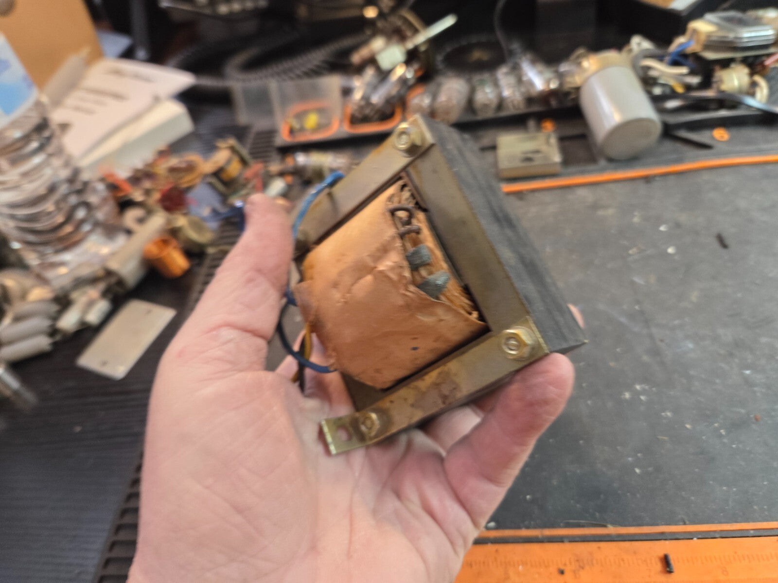
Each listing states that the part is used and is sold as a single component, not a complete radio. For a working example to compare VA and current ratings against, see the Ac Power Transformer For Mustang Ii Base Station Cb Radio. For background on why buying tested vintage electronics lowers your risk, read Why Buy Tested Vintage Electronics: A 2026 Buyer's Guide.
Find the transformer that fits your schematic, then add it to your cart.
Frequently Asked Questions
What is the difference between a radio power transformer and an audio output transformer?
A power transformer steps household AC voltage, typically 120 volts in the United States, up or down to supply the radio's rectifier, filaments and high-voltage plate supply. An audio output transformer sits between the output tube and the speaker, matching the tube's high plate impedance to the speaker's low impedance, commonly 4, 8 or 16 ohms. The two parts look similar on the chassis but are not interchangeable, so check the schematic label and winding leads before ordering. Scott Radio & Electronics lists used Power Transformers for several Browning, Lafayette and RadioShack models, such as the Browning R-27 at $40.00 and the Lafayette Comstat 25B at $25.00, so confirm the markings against your radio first.
How do I know which vintage radio transformer fits my radio?
Start with the model's schematic or service data, which lists primary input voltage, secondary voltages and current ratings. Compare the donor transformer's mounting footprint, lead count and color coding with your chassis, since a transformer with the right voltages can still fail to fit. Used parts are sold as-is, and compatibility with other models is not always verified, so match the markings and dimensions yourself before installation. Scott Radio & Electronics notes this on each listing, so use the photos and description to check leads and mounting before you buy.
How do I test a radio power transformer before I power up the radio?
Unplug the radio and use a multimeter to check continuity across each winding, reading a low, consistent resistance on the primary and secondary windings and an open circuit between windings and the core. A reading of zero ohms or an erratic value suggests an internal short, while infinite resistance on a winding indicates a broken coil. Check insulation between each winding and the metal frame, and keep the radio disconnected from mains while you work. Test the transformer on a bench before installing it, and if it runs warm or hums loudly when energized through a variac, do not install it.
What is the 80% rule for transformers, and does it apply to vintage radios?
The 80% rule is a common rule of thumb for transformer loading: continuous current draw should stay at or below about 80% of the rated current for a sustained load, leaving margin for heat and voltage variation. Applied to a vintage radio, it means choosing a power transformer whose VA rating comfortably exceeds the radio's measured or schematic current demand, rather than sizing it exactly to the rating. Use the schematic's listed current figures as your baseline and add a safety margin before selecting a replacement.
