

Identifying Vintage CB Radio Channel Boards: 2026 Guide
Table of Contents
- Step 1: Gather Your Tools and Prepare for a Safe Inspection
- Step 2: Read the CB Radio Channel Board Markings
- Step 3: Identify Vintage CB Radio Crystals and PLL Boards
- Step 4: CB Radio Circuit Board Testing and Documentation
- Step 5: Check CB Radio Board Compatibility Before You Buy
- Common Mistakes When Identifying Vintage CB Radio Channel Boards
- Conclusion: From Identification to Installation
- Frequently Asked Questions
Last Updated: October 14, 2026
Step 1: Gather Your Tools and Prepare for a Safe Inspection
Identifying vintage CB radio channel boards starts with a safe, well-lit inspection before any power touches the chassis. The difference between a clean identification and a damaged radio usually comes down to preparation.
A channel board is the circuit board inside a CB radio that holds the channel selector switch and the components that set each channel's frequency. In older radios, that board may carry crystals.

Gather these tools first:
- A non-magnetic screwdriver set (Phillips and flathead)
- A multimeter for continuity and voltage checks
- A magnifying glass or jeweler's loupe
- A soft brush and isopropyl alcohol for cleaning
Step 2: Read the CB Radio Channel Board Markings
Board markings are your fastest path to identifying a vintage CB radio channel board, but only if you know how to decode them. Most manufacturers stamped or printed a model number, a part number, and sometimes a revision code directly on the board itself.
Look for these markings in this order:
- Board part number printed near the board edge or silkscreen (this is the number you cross-reference)
- Radio model number stamped on the board or on a sticker (this ties the board to a chassis)
- Revision code (often a letter or two-digit number) showing production era
- Manufacturer logo or initials
- Date codes on capacitors and other components
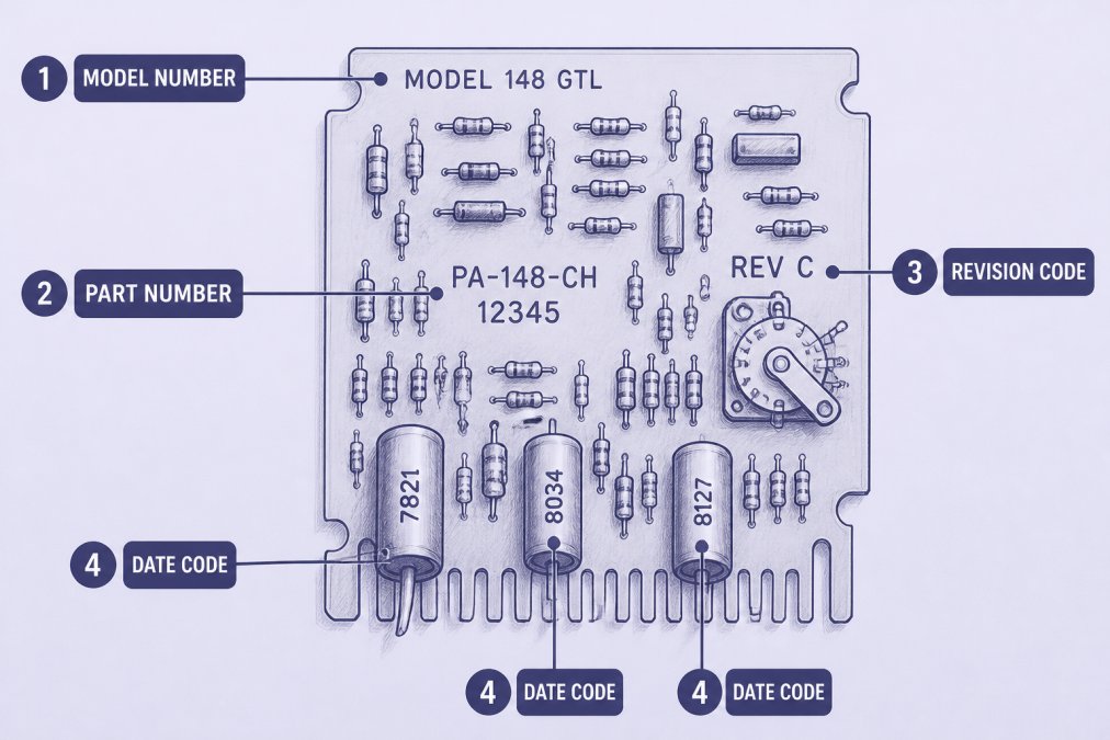
How to Decode the Numbers
Vintage CB board numbers follow loose conventions rather than a single standard. A few patterns show up repeatedly:
- "PC-" prefixes (PC-145, PC-202) are common on boards from the 1960s and 1970s and usually indicate a printed circuit part number, not a radio model.
- Numeric-only stamps (for example, 7042 or 12345) are often internal factory numbers tied to a production run, and they rarely cross-reference cleanly to a retail model.
- Revision letters (REV A, REV B, REV C) tell you the board was updated during the model's life. A REV A board and a REV C board for the same radio may not interchange.
A board marked "PC-145" from a PACE unit will not match a Lafayette board, even if both are 23-channel radios. The board markings tell you which radio family it belongs to, and the revision tells you which production slice of that family.
Cross-Referencing Without a Catalog
There is no single authoritative public database of vintage CB board numbers, so cross-referencing is a manual process. A workable method:
- Photograph the board and note every number, letter, and logo.
- Search the part number alongside the radio brand and model (for example, "PACE CB-145 PC-145 board").
- Check collector forums and service-manual scans, which often list board numbers alongside schematics.
- Compare the board's physical layout (switch type, connector count, crystal count) against photos of known boards.
- When two boards share a part number but differ in revision, trust the revision code over the part number.
When the Markings Are Gone
Worn or missing markings are common on radios that saw decades of use. If the board is blank, work backward from the radio:
- Check the front panel and chassis for a model number, then look up that model's known board revisions.
- Count the channels (12, 23, or 40) and note the switch type (rotary or pushbutton).
- Count crystals if present, or locate the PLL chip and read its part number.
- Match the connector layout and mounting-hole pattern against photos of known boards for that model.
If you cannot match a board to a model, treat it as unidentified rather than guessing. A wrong-fit board can damage the selector switch or the PLL chip, and those parts are often unobtainable for older radios.
Step 3: Identify Vintage CB Radio Crystals and PLL Boards
There are two main types of vintage CB radio channel boards, and telling them apart changes how you test, repair, and replace them. The table below is a starting point, but the real skill is reading the board visually before you touch a meter.
| Feature | Crystal Board | PLL Board |
|---|---|---|
| Components | Row of metal crystal cans | One large IC chip |
| Channel count | Usually 12 or 23 | Usually 40 |
| Spacing | 10 kHz channel steps | 10 kHz channel steps |
| Era | 1960s-1970s | Late 1970s onward |
| Replacement | Swap individual crystals | Replace whole board |
A Visual Workflow for Telling Them Apart
Work through these checks in order. Stop as soon as you have a confident answer.

- Look for a row of metal cans. Crystal-controlled boards use one or two quartz crystals per channel, soldered in a line. Each can is a transmit crystal or a receive crystal tuned to that channel's frequency. A 23-channel crystal radio often carries 46 crystals (one transmit and one receive per channel).
- Look for a single large IC. PLL synthesizer boards use an integrated circuit chip to generate all channels electronically. You will see one large chip and fewer discrete components.
- Count the channels. A 12- or 23-channel radio is more likely to be crystal-controlled; a 40-channel radio is almost always PLL. This is a tendency, not a rule.
- Read the chip part number. If you find a large IC, read its part number and search it. PLL chips from the late 1970s and 1980s are well documented in service literature.
- Check the selector switch. Rotary switches are common on both types, but pushbutton and digital-selector radios are almost always PLL.
Why the Distinction Matters for Compatibility
The frequency range for CB radios runs from 26.965 MHz to 27.405 MHz, with 10 kHz spacing between channels. A 23-channel radio covers fewer of those steps than a 40-channel unit, and the board must match the radio's design, not just its channel number.
- Crystal boards are repaired by swapping individual crystals. If one channel is dead, you replace that channel's transmit or receive crystal rather than the whole board.
- PLL boards are repaired at the board level. If the PLL chip fails, the whole board usually has to be replaced, and replacements may not exist for every model.
- A crystal board will not work in a PLL radio, and vice versa. The two designs use different frequency-generation methods and different wiring to the selector switch.
A Note on Channel Plans
Most vintage radios sold in the United States follow the standard 40-channel plan (channels 1 through 40, 26.965 MHz to 27.405 MHz). Older 23-channel radios use a subset of that plan, and 12-channel radios use an even smaller subset. If you are working on a radio of uncertain origin, confirm the channel plan before assuming a board will match. A board built for a different plan may fit physically but tune to the wrong frequencies.
Step 4: CB Radio Circuit Board Testing and Documentation
Testing a vintage CB radio circuit board means checking continuity, voltage, and component health without guessing. Document everything as you go.
Start with a visual pass:
- Look for bulging or leaking capacitors
- Check for cold solder joints or cracked traces
- Note any burn marks or discoloration
- Photograph the board from both sides
Then test with your multimeter:
- Set the meter to continuity mode
- Check the channel selector switch contacts for clean switching
- Verify voltage at the board's power input
- Test each crystal or the PLL chip's power pin
Record your readings in a notebook. Note the board's model number, part number, and any revision code.
PACE CB-145 Channel Selector Switch Board CB Radio Parts Tested →
For a deeper reference on CB radio fundamentals, the FCC Citizens Band Radio Service rules explain the 27 MHz band and channel assignments.
Step 5: Check CB Radio Board Compatibility Before You Buy
Board compatibility comes down to three things: model match, revision match, and connector layout.
Before buying a replacement board, confirm:
- The donor radio's model number matches yours
- The board's revision code is compatible
- The mounting holes and screw positions line up
- The wire lead count and terminal layout match
- The channel selector switch type is the same
We keep a curated selection of tested vintage CB radio channel boards organized by brand and model. For example, our PACE CB-145 Channel Selector Switch Board is a tested rotary switch with its attached board, removed from a PACE CB-145.
For Lafayette owners, we stock the Lafayette Telsat SSB-75 Channel Selector Crystal Board at $25.00.
FANON Fanfare 100PLL owners can use our rotary channel selector switch at $25.00, a multi-contact switch with cut wires from a working unit.
And if you're restoring a FOX radio, our numbered channel dial and selector assembly at $20.00 includes the dial, shaft, lamp holder, and metal support.

Common Mistakes When Identifying Vintage CB Radio Channel Boards
The biggest mistake is assuming all 23-channel boards are interchangeable. They are not. Board layout, revision codes, and connector positions vary by manufacturer and production year.
Other common errors:
- Powering up a radio before inspecting the board
- Skipping the revision code and buying a mismatched board
- Confusing crystal boards with PLL boards
- Forgetting to photograph the board before removal
- Assuming a 40-channel board fits a 23-channel radio
A 12-channel, 23-channel, and 40-channel radio each use a different frequency plan and channel count. The board must match the radio's design, not just its channel number.
If you're unsure which part you need, our founder Jack Scott personally oversees the customer experience to ensure that your purchase receives the care and attention it deserves.
Conclusion: From Identification to Installation
Identifying vintage CB radio channel boards takes patience, the right tools, and a careful eye for markings and component types.
SCOTT RADIO & ELECTRONICS stocks tested, model-specific boards organized by brand and model, so you can find the part that actually fits your radio.
Get started with SCOTT RADIO & ELECTRONICS and bring your classic radio back to life with parts that fit the first time.
Frequently Asked Questions
How do I identify a vintage CB radio channel board?
Start by locating the model number on the radio's back or bottom label, then open the case and find the channel board. Look for printed markings such as part numbers or revision codes. Count the number of channels the radio supports (12, 23, or 40) and check whether the board uses crystals or a PLL chip. Compare these details with service manuals or online references for your specific model.
What do the crystals on a vintage CB radio channel board do?
Crystals on a vintage CB radio channel board generate the precise frequencies needed for transmit and receive. Each channel typically requires a separate crystal pair, one for transmit and one for receive. The frequency is usually stamped on the crystal can, such as 26.965 MHz for channel 1. If a crystal is missing or damaged, that channel will not work.
Are vintage CB radio channel boards interchangeable between models?
No, vintage CB radio channel boards are rarely interchangeable between different models or brands. Even if two radios share the same channel count, the board's mounting holes, wiring harness, and switch configuration often differ. Always match the board's part number and physical layout to your exact radio model.
How can I tell whether a vintage CB radio channel board is damaged?
Look for visible signs such as burn marks, cracked solder joints, bulging capacitors, or corrosion on the board. Use a multimeter to check continuity across the channel switch contacts. If the radio powers on but only some channels work, the board may have a faulty crystal or a broken trace. Testing before powering up helps avoid further damage.