

7 Steps to Test Vintage Radio Capacitors Safely
Last Updated: November 2, 2026
Quick Summary
To test vintage radio capacitors, discharge them fully first, verify zero volts with your meter, then isolate the cap and screen it with a multimeter resistance check for shorts and opens. Follow up with a capacitance meter, ESR meter, or leakage tester, since a resistance check cannot confirm value, leakage, or ESR.
- Filter capacitors in tube radios can hold 200 to 450 volts or more after shutdown.
- Discharge with a 1k to 10k ohm resistor rated at least 5 watts, then verify zero volts.
- A multimeter reading that stays near zero ohms means the cap is shorted and must be replaced.
- Test each section of a multi-section filter can separately against its own marking.
- Replace paper, wax-coated, swollen, or leaking caps; test mica caps and leave good ones alone.
Table of Contents
- Why Vintage Radio Capacitors Fail and What Testing Tells You
- How to Discharge a Capacitor Safely Before You Test
- How to Identify Capacitor Types by Markings and Appearance
- How to Test a Capacitor With a Multimeter
- How to Test Electrolytic Capacitors and Filter Cans
- How to Test Paper Capacitors and Molded Types
- When to Test vs Replace and Where to Source Parts
- Frequently Asked Questions
Why Vintage Radio Capacitors Fail and What Testing Tells You
Old capacitors die quietly. That is the problem. A vintage radio can look perfect on the shelf and still hum, crackle, or go completely silent because one paper capacitor drifted or an electrolytic can dried out.
Knowing how to test vintage radio capacitors saves you from guessing.
Here is what most guides get wrong. They treat every capacitor the same. In a tube radio, a paper coupling cap and a multi-section filter can fail in completely different ways and need different tests. We group vintage radio capacitors into three practical families, and the test changes with each one:
- Paper and molded caps in the signal path, which drift and leak
- Mica caps, usually stable but occasionally cracked
- Electrolytic filter cans, which dry out and hum
Below, we walk through the steps used on most antique radios, from safety to sourcing a replacement.
How to Discharge a Capacitor Safely Before You Test
Discharging a capacitor means draining its stored DC voltage to zero before you touch it. In a tube radio this is not optional.
Here is a common discharge procedure for tube chassis:
- Unplug the radio and pull the line cord completely out of the outlet. Do not rely on the power switch.
- Wait several minutes after shutdown. Some supplies have bleeder resistors that drain the main filter can, but many vintage sets do not, so waiting alone is not enough.
- Clip one end of a discharge resistor to the chassis with an insulated lead. A 1k to 10k ohm resistor rated at least 5 watts works for most filter cans; a higher value discharges more slowly but is gentler on the cap and the terminals.
- Touch the free end of the resistor to each capacitor terminal and hold it there for several seconds. For a multi-section can, discharge every section to the chassis.
- Verify zero volts with your meter set to DC volts before you touch anything. Probe from the cap terminal to the chassis and confirm the reading is near zero. If it is not, repeat the discharge and recheck.
- Recheck again after a minute. A cap that creeps back up to a significant voltage is leaky or is being fed by another charged section and needs further attention.
A few practical cautions. Do not short a charged can directly with a screwdriver; the arc can pit the terminals, weld the tool to the cap, and startle you into a slip. Electrician Insulation Multi Purpose Repair Tool Screwdriver Set provides insulated tools for working safely around capacitors. Use the resistor.
Once the cap is discharged and verified at zero volts, you can isolate it from the circuit and move on to testing. Skipping the verification step is the most common way restorers get shocked by a radio that has been off for days.
How to Identify Capacitor Types by Markings and Appearance
Identifying a capacitor means matching its markings and body style to a known type. In vintage radios, the look of the part often tells you more than the label does.
Start with appearance. Paper capacitors are usually wax-coated tubes or flat molded rectangles. Mica caps are small, flat, and often rectangular with colored dots. Electrolytic cans are the tall metal cylinders mounted on top of the chassis, sometimes with several sections inside one case.
Reading Capacitance and Voltage Ratings
Capacitance is measured in microfarads (uF) or picofarads (pF), and the voltage rating tells you how much the cap can take before it breaks down. Read both.
Old markings can be cryptic. You may see ".05" meaning 0.05 uF, or "500V" for the rating. Some caps use color codes instead of printed numbers. Write down the value and rating before you remove anything.
Visual Inspection for Leakage, Bulging, and Cracks
A visual check catches the obvious failures before you even reach for a meter. Look for:
- Wax dripped down the side of a paper cap
- Bulging or split seams on an electrolytic can
- Cracks in a molded or mica body
- Crusty residue around the terminals
Any of these means the cap is suspect. A clean look does not prove it is good, but a bad look usually means replacement.
How to Test a Capacitor With a Multimeter
A multimeter resistance check is the quickest way to catch a grossly failed capacitor, but it is a screening test, not a verdict. You are watching how the cap charges through the meter's internal resistance.
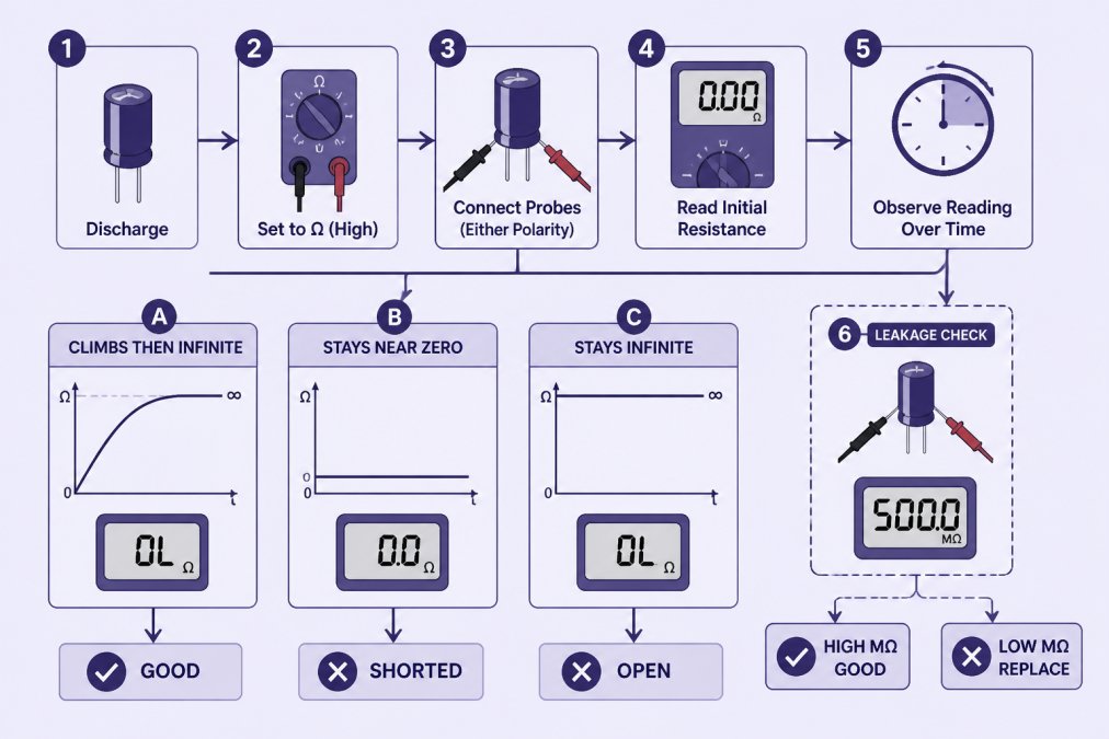
Set your meter to resistance, isolate the cap from the circuit, and connect the test leads across its terminals. On an analog meter the needle swings toward zero, then climbs back as the cap charges.
Lafayette Comstat 25B Multi-Section Can Capacitor →
What the Reading Actually Tells You
A climbing reading proves the cap is not shorted and not fully open. It does not prove the cap is good. The resistance check cannot measure capacitance value, cannot measure leakage current under operating voltage, and cannot measure ESR. A paper cap that reads a healthy climb on a multimeter can still leak DC into a grid circuit and ruin the radio's bias. That is why most practitioners treat a passing resistance check as a reason to keep testing, not a reason to stop.
Use these rough thresholds to interpret what you see:
- Stays near zero ohms: shorted. Replace.
- Reads infinite from the first touch: open. Replace.
- Climbs and settles high: not shorted or open, but value and leakage are still unknown. Test further.
- Climbs then drifts back down: leaky or unstable. Replace.
The In-Circuit Testing Trap
In-circuit testing misleads you because other components in parallel skew the reading. A resistor across the cap, a parallel cap in a can, or a path through the tube heaters can all make a bad cap look good or a good cap look bad. Lift one leg when you can. For a multi-section can, test each section against its own terminal and the chassis, not across the whole can.
Choosing the Right Test Method
Different tests reveal different failure modes, so match the method to the question you are asking:
- Multimeter resistance check: catches shorts and opens. Fast, cheap, and useful as a first screen.
- Capacitance meter: measures actual value against the marked value. Catches drift and dried-out electrolytics.
- ESR meter: measures equivalent series resistance. Catches electrolytics that have lost their ability to filter even when capacitance still reads in range.
- Leakage tester: applies voltage and measures leakage current. The only method that catches a paper cap that passes a cold resistance check but breaks down under operating voltage.
A simple resistance check will not catch every leak, only gross failures. If the radio hums, crackles, or loses bias after warm-up, move past the multimeter to a capacitance and leakage test before you decide the cap is good.
How to Test Electrolytic Capacitors and Filter Cans
Electrolytic capacitors and multi-section filter cans are the parts most likely to fail in a vintage radio, and they are the ones that cause hum. Test them for capacitance and leakage, not just resistance.
Multi-section cans hold several capacitors in one case, so test each section separately against its own marking. If you need a reference point or a replacement, this Lafayette Comstat 25B multi-section can capacitor is a used original part from our catalog, sold at $15.00.

The hum test is practical too. A loud 60-cycle hum that stays after warm-up often points straight at the filter can. Replace rather than restuff when the can is badly swollen.
How to Test Paper Capacitors and Molded Types
Paper capacitors are the quiet killers in antique radio restoration. They drift in value and leak DC voltage into circuits where it does not belong, and they can do it while still passing a basic resistance check.
Test them out of circuit. Check capacitance against the marked value. Then check for leakage with a meter or a proper capacitor tester. A paper cap that reads near its value but leaks current is still bad.
Mica caps are the exception. They usually hold up well, so test them and leave good ones alone.
When to Test vs Replace and Where to Source Parts
Test when you are diagnosing a fault and want to know which part failed. Replace when the cap is paper, wax-coated, swollen, or already leaking. In a full restoration, many restorers replace paper and electrolytic caps as a matter of course and test the mica ones. Replacing Paper Cone Vintage Radio Speakers covers the related task of speaker replacement in vintage radios.
Sourcing is the hard part. You need a part that matches mounting, connectors, and markings.
| Symptom | Likely Fault | Action |
|---|---|---|
| Loud hum after warm-up | Filter can dried out | Test capacitance, replace |
| Crackle or weak signal | Paper cap leaking | Test leakage, replace |
| Dead section | Open capacitor | Check reading, replace |
| No obvious fault | Drifted value | Test capacitance |
Frequently Asked Questions
Can you test a capacitor without removing it from the circuit?
In-circuit testing gives unreliable results because parallel paths in the radio add resistance and capacitance that skew your reading. A capacitor that looks good in circuit may be leaking, and one that looks bad may test fine once isolated. For any vintage radio capacitors you suspect, desolder at least one lead before testing. The only exception is a quick charge-holding check on filter cans, and even that is a rough screen, not a verdict.
How can you tell if a vintage radio capacitor is bad?
Three signs point to failure: a multimeter resistance reading that stays near zero (shorted), a reading that never climbs (open), or a reading that settles at a finite value instead of climbing toward infinity (leaky). Physical clues count too, including wax seepage, bulging cans, cracked molded cases, and corrosion on the leads. Paper and electrolytic types in tube gear often fail even when they show no outward damage, so test before powering up.
Do old paper capacitors need to be replaced even if they test okay?
Yes, in most tube radio restoration work. Paper capacitors absorb moisture over decades and develop leakage current that a basic ohmmeter check can miss at full operating voltage. A capacitor that reads high resistance on a meter may still break down under 200 to 400 volts in the circuit. Many restorers replace all paper and molded capacitors on sight and reserve testing for confirming which ones already failed.
What is the safest way to test a tube radio capacitor?
Unplug the radio, then discharge every filter capacitor through a resistor to ground before touching anything. Use one hand where possible, keep a meter rated for the voltages present, and never probe a live chassis. If you must measure voltages during troubleshooting, use a clip-on lead so you are not holding a probe near high voltage. Replace suspect vintage radio capacitors with parts rated at or above the original voltage.
Testing vintage radio capacitors is the step that separates a repair that lasts from one that comes back. If you are chasing a hard-to-find replacement, SCOTT RADIO & ELECTRONICS stocks parts organized by brand and model, with personal service from our founder, Jack Scott. Get started with SCOTT RADIO & ELECTRONICS and find the exact component your radio needs.
